|
2019-04-26
C4e BOSE Connectors
The wiring harness in the early (1984 thru 1989) C4 Corvette employs several
different connectors to interface with the BOSE head unit. These connectors
and how they are used with the Comvette system are described below:
NOTE: My factory service manual for 1988 shows the connector
shell orientation incorrectly for connectors C3, C4 and C1. The wire colors
and pin labels appear to be correct. The connector illustrations below for
connectors C3, C4 and C1 are drawn as they actually appear in my 1988 Corvette.
I don't know if this error appears in factory service manuals from other model
years.
-
Connector 3 (blue shell), REAR SPEAKERS

-
Pin L: SHIELD
-
Pin K: LT BLUE & YELLOW, Common
-
Pin J: BROWN, Left Line Level Audio Input
-
Pin H: DARK BLUE, Right Line Level Audio Input
-
Connector 4 (white shell), FRONT SPEAKERS

-
Pin D: GRAY & GREEN, Common
-
Pin C: SHIELD
-
Pin B: TAN, Left Line Level Audio Input
-
Pin A: LIGHT GREEN, Right Line Level Audio Input
-
Connector 1 (black shell), POWER AND OTHER

-
Pin E: PINK, Power Antenna
Causes power antenna to extend/retract. Applying 12 volts to this line causes the antenna to extend.
Removing the 12 volt power from this line causes the antenna to retract. Comvette controls the power
antenna through this line.
-
Pin F: YELLOW, Power Input
+12 volts switched. Powers the BOSE head unit only when ignition is in ACCESSORY or RUN position.
Used by the Comvette Power Manager to detect when the ignition is in ACCESSORY or RUN
position.
-
Pin M: GRAY, Interior Lights Dimming
+12 volts variable. Rotating headlight knob causes a rheostat built into the head light switch to provide
a variable voltage to the dashboard lights for varying brightness levels. Not currently by used by Comvette
but may be used in the future.
-
Pin G: BLACK, Ground
System ground.
-
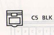
Connector 2 (black shell), AMPLIFIER RELAY

-
Connector 5 (black shell), DISPLAY DIM SIGNAL

-
GRAY/WHITE, Display Dim Signal
PWM (Pulse Width Modulation) signal to control the brightness level of the digital display on the
C68 electronic heating/ventilation/air conditioning control unit. Not currently used but may be
used in the future.
-
Connector 240 (? shell), CLOCK POWER & DIM DISPLAY
-
Pin A: ORANGE, Clock Power
+12 volts constant. Used to keep the Comvette Power Manager running at all times. Also
used by the Power Manager to supply power to the Comvette system when ignition is in ACCESSORY
or RUN position.
-
Pin B: BROWN, Dim Display
Headlight/Parking light ON/OFF indicator. Not currently used but may be used in the future to
change the Comvette touch-screen display to night mode color scheme.
NOTE: The "line level" audio inputs listed above can be driven by the "line out" or earbud connections of
most personal audio equipment such as an iPod, or generic MP3 player or other electronics with line
level or earbud outputs. The BOSE speaker/amplifiers have a fixed gain like most power amps and will
amplify whatever signal they receive, so the volume must be controlled at the audio source.
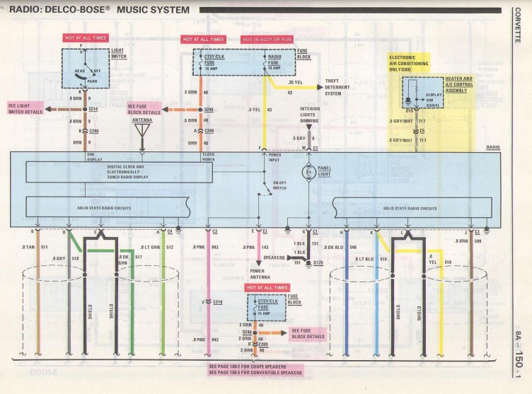
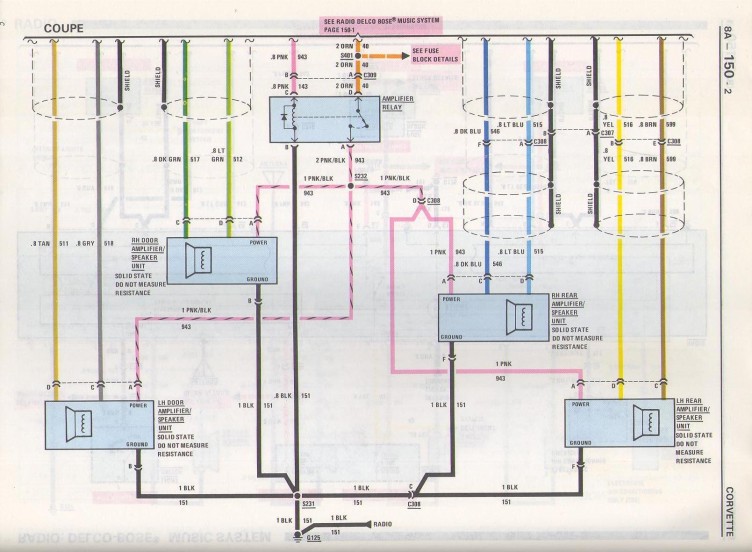
The BOSE head unit OEM wiring diagrams:


| Wire Size Conversion |
| Metric (mm²) |
AWG |
| .22 |
24 |
| .35 |
22 |
| .5 |
20 |
| .8 |
18 |
| 1.0 |
16 |
| 2.0 |
14 |
| 3.0 |
12 |
| 5.0 |
10 |
| 8.0 |
8 |
| 13.0 |
6 |
| 19.0 |
4 |
| 32.0 |
2 |
NOTE: A number of early C4 Corvette owners have questioned whether or not they can reuse the
existing speaker wiring when removing the entire BOSE system (head unit and speakers/amplifiers)
and replacing them with an aftermarket head unit and speakers.
According to the GM service manual wiring diagrams above, the speaker wiring is metric .8 mm²
which is essentially the same as 18 AWG. 18 AWG should be adequate for a typical car stereo system
(unless you are pushing enormous amounts of power from your new head unit to your speakers). Reusing
the existing car wiring is a lot easier than pulling new wire. Consider reusing the existing wiring
if possible.
|
 Shopping Cart
 Shopping Cart
